3d Construction
A. Extrude an object
1. Start a new drawing using the "A" size Triton template
There are two ways of extruding objects:
a. Change the thickness of an object - can be done to any promitive object (line, arc, circle, point, pline, text)
b. Use the extrude command (ext) after drawing a closed polyline or a circle
2. Do both types with several lines, arcs, circles, points, rectangles, and text
3. Shade using Gourad method and print.
4. Using the second method of extruding, create several rectangles, polygons, closed polylines fit to a curve, and circles. Use the "uni" and "su" commands to unify and subtract objects to or from one another.
5. To place text on a drawing that is shown in a "viewpoint" other than the plan, you must create a temporary User Coordinate System parallel with the viewpoint - to do this, type UCS<RET> v<RET> Now create the text and it will be parallel with the paper.
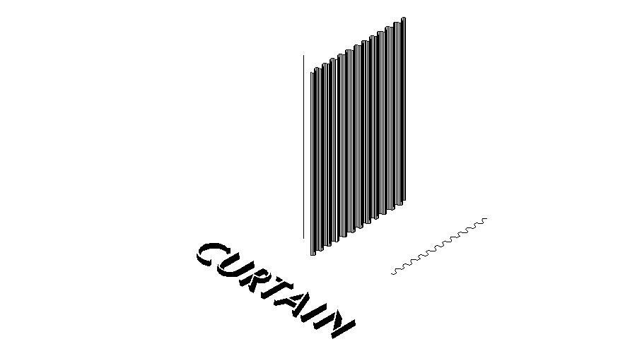
B. Tabulated surfaces - the TABSURF Command: Drawing a Curtain
1. Start a new drawing
using the "A" size Triton template
2. Draw a circle with a 3" diameter
3. Cut this circle in half vertically, by drawing a vertical line from the top
QUADrant of the circle through the lower edge, then using the TRIM: command,
with the line as the cutting edge, trim off one side of the circle. Erase
the line.
4. Mirror the half circle toward the top, using the top point of the arc as
the first point of the mirror line and a point to the right (or left) of it
as the second point of the mirror line.
5. Mirror this new arc to the left (erasing the original mirrored arc).
This will complete an "S" curve consisting of two arcs.
6. Array these two arcs vertically, 12 rows, with row spacing equal to distance
from top to bottom of both arcs (6").
7. Pedit one of the arcs in this group, and convert it to a Pline, join it to
all the other arcs, thus creating a long curvy Pline, made up of 24 arcs.
8. Set the Vpoint to the "Chicago" point of view (VPOINT<RET>1,-1,1<RET>).
9. Make a view of this Vpoint called "1" (-View<RET>s<RET>1<RET>).
10. Draw a vertical line anywhere on the drawing, 10' high (10' in the Z direction).
11. From pull-down menu, select DRAW, then Surfaces, then Tabulated Surfaces,
pick the Pline, then pick the vertical line.
12. Put title block on this resulting drawing, print it, and turn in. Title
block should contain the name of the project: "Curtain", your name, today's
date, Course number, and instructor's name.
C . RULESURF Command: Eyebrow window
1. Start a new A-size drawing
2. Draw a line 20' long, from 0,0 to 20',0.
3. Copy this line 20' in the Y direction.
4. Change UCS to Front view UCS
5. Set the Vpoint to the "Chicago" point of view (VPOINT<RET>1,-1,1<RET>).
6. Make a view of this Vpoint called "1" (View<RET>s<RET>1<RET>).
7. Draw a smooth ogee curve using the Pline command from the left point of the
first line just drawn to a point 6' above the middle of this line.
8. Mirror this smooth curve Pline to fill out the profile of the eyebrow.
9. Pedit one of these Plines and join it to the other to form one single Pline.
10. Set the variable Surftab1 to 30: Type surftab1, then type 30<RET>
11. Type RULESURF <RET>
12. Pick first defining curve as the curved Pline (pick toward one end).
13. Pick second defining curve to be the line (pick toward the same end).
14. Put title block on this resulting drawing, plot out, and turn in.

D. REVSURF Command: "Serpentine Greenhouse"
1. Start a new A-size drawing
2. Change UCS to Front view UCS and switch to the plan view.
3. Start with a rectangle and create a greenhouse profile, 20' long, 12' high,
with 6' radius curves at the top left and right corners.
4. Pedit one of the lines or arcs which were used to form greenhouse profile
to turn it into a Pline. Join it to all the other lines and arcs to make
one Pline out of all of them.
5. Draw vertical line from point 60',0,0 to point 60',40',0, to make an axis
of rotation.
6. Set the Vpoint to the "Chicago" point of view (VPOINT<RET>1,-1,1<RET>).
7. Make a view of this Vpoint called "1" (View<RET>s<RET>1<RET>).
8. Change value of variable Surftab1 to 12 and Surftab2 to 6.
9. Type REVSURF<RET>
10. Pick the Pline representing the profile of the greenhouse for the "path
curve"
11. Pick the vertical line for the "axis of revolution."
12. Type 0 for the "start angle" and 90 for the "included angle."
13. Change UCS to World UCS
14. Mirror the greenhouse mesh to the right and then up to make an "S" curve.
15. Add a ground plane using a region
16. Position a sun and render drawing
17. Create a perspective view and save it as a view
18. Apply glass material to greenhouse
19. Add entourage (a figure and plants)
20. Render to a file
21. Print in color Paint Shop Pro
For reference, standard material files are kept in the following folder:
C:\Documents and Settings\All Users\Application Data\Autodesk\Autodesk Architectural Desktop 2004\R 16.0\enu\Textures
The "library files" which contain descriptions of entourage (people, trees, and signs) are contained in the following folder:
C:\Documents and Settings\AT150\Application Data\Autodesk\Autodesk Architectural Desktop 2004\R 16.0\enu\Support

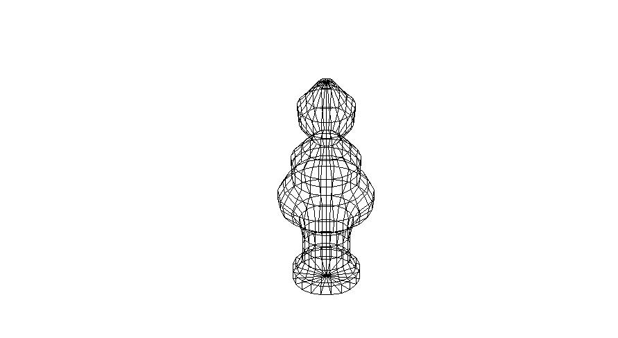
E . REVSURF Command: "Chess pieces"
1. Using the principles
applied in the above project, and using the Front view UCS, draw several Pline
profiles which form hourglass or chess pieces profiles, use an axis of revolution
which passes through both ends, and revolve the profile to create several (at
least 5) 3d objects of varying sizes and shapes.
2. Note that different values of surftab1 will make finer or cruder surfaces.
3. Create a 3d checkerboard in plan with green and red squares (8 x 8).
4. Place chess pieces on this checkerboard.
5. Put title block on this resulting drawing, print out, and turn in.
F . EDGESURF Command: "Spider webs"
1. Draw symmetrical
2 arcs in plan - they should not touch each other
2. Switch UCS to Front elevation UCS
3. Change VPOINT to Chicago
4. Draw 2 arcs in front elevation, connecting the endpoints to the endpoints
of the previous arcs drawn in the World coordinate system. Make one of
the arc bulges smaller than the other by using grips.
5. Type EDGESURF <RET>
6. Pick each of the "edges" (the arcs) successively.
7. Put title block on this resulting drawing, plot out, and turn in.

G . 3dFACE: command:
1. Using the Front Elevation
UCS, draw the elevation attached.
2. Draw 3dFaces on the surface of this elevation, making sure to use the "Invisible"
mode of 3dFace at all faces which are not along object lines.
3. Switch to the World UCS.
4. Array Polar the resulting elevation and faces so that a complete enclosure
is created on four sides, creating a cross-gable building.
5. Set the Vpoint to the "Chicago" point of view (VPOINT<RET>1,-1,1<RET>).
6. Make a view of this Vpoint called "1" (View<RET>s<RET>1<RET>).
7. Draw lines connecting the tips of the gables to one another, thus creating
the roof ridges.
8. Draw 3dFaces to form the roof planes (hint: draw one pair and array
them)
9. Put title block on this resulting drawing, and plot out using hidden lines.
10. Do the same exercise, except this time use 3d solids to form the sides and
roof. Make all solids 6" thick. Cut holes through the solids.
Add a 3d figure and tree from the standard blocks.
11. Label them and turn in both examples.
