CUSTOMIZING AUTOCAD
Customization allows a user to make the program appear and function the way
that is appropriate for the type of work being done. For instance, making drawings
of a building is quite different from making drawings of an automobile part.
Not only is the scale of the object drawn differently, but the conventions of
drafting are significantly different between architecture and mechanical parts.
AutoCAD "out-of-the-box" is set up primarily for mechanical drafting,
that is, drawing small parts for machinery using the metric system because that
is the type of drafting is the most practiced in the world. In order to make
the drafting environment correct for architectural drafting conventions, several
important changes must be made. These customization changes are relatively simple
to accomplish, and involve the following three types of changes:
1. Customizing the User Interface by setting menus, toolbars and palettes that are displayed. The CUI ("Customized User Interface") settings can be saved for future use as a "Workspace."
2. Creating a "Template" file that has desirable variables set, as well as layers, text styles, dimension styles, layouts and plotting standards created specifically for architectural drafting purposes. Your Template file can then be used to open new drawings to eliminate having to set up these changes again in the future.
3. Creating a user "Profile" that will save the way you want the screen to look and where AutoCAD will search for files. Your personal Profile can be loaded when you start a new AutoCAD session at whatever computer you are working.
CUSTOMIZED
USER INTERFACE (CUI)
Since the release of ACAD 2006, AutoCAD now allows you to
set up your own arrangement of menus, toolbars and palettes through the CUI
command.
How to customize Menus in AutoCAD or ADT:
1. First make a copy of all CUI files on your computer and store them in a safe place, in case you make a mistake and want to restore the former version of each file. All existing customization files have the file name extension of *.cui and are located at in the Support Folder at C:/Documents and Settings/AT150/Application Data/Autodesk/ADT2007/enu/Support
2. In AutoCAD or ADT, type CUI<RET> The Customize User Interface dialogue box will appear. This dialogue box has a "Customize" tab and a "Transfer" tab. Use the "Customize" tab to modify the current loaded CUI file. Use the "Transfer" tab to create your own portable CUI file, which you may take with you to another computer. There is always one menu file that is the so-called "Main CUI file." In AutoCAD it is the file "Acad.cui." In Architectural Desktop, it is "ADT.cui."
3. In the "Customize" tab, under the header "Customizations in All CUI Files" select from the pull-down list "All Customization Files."
4. Click once on "Partial CUI Files."
5. Right Click on "Partial CUI Files and then select "Load Partial Customization File."
6. You will be prompted to select an existing
customization file to load.
7 . Select the customization file that you want to load. If you are using vanilla AutoCAD this might be the acetmain.cui, which is the Express tools. If you are using ADT, this might be ADTDesign.cui, ADTDocument.cui, acetmain.cui, or Acad.cui. The last one is the main AutoCAD menu which contains many pull-down menus that are not included in ADT.
8. Once again, In the "Customize" tab, under the header "Customizations in All CUI Files" select from the pull-down list "All Customization Files."
9. Double-click on the line "Partial CUI Files." This will bring up a list of CUIs that are loaded.
10. Expand the Menus in the partial CUI file that you want to modify by double-clicking on it.
11. Delete any Menus that you may not want to appear in the pull-down Menu line at the top of the AutoCAD screen. For instance, if you are partially loading the Acad.cui Menu, there are some pull-down Menus that also appear in the ADT.cui Menu. It would be confusign to have two "File" pull-down Menus, for instance. Unfortunately, the way the pull-down Menus line up across your drawing screen is solely controlled by AutoCAD and you cannot change it. I suggest leaving ADT or ACAD as the main CUI menu files and add the other partial Menus in the order you want them to appear. This is not a perfect solution, but it is the best you can do at this stage in the evolution of this nifty new addition to the program.
12. It is not necessary to delete duplicate Toolbars in your partial CUIs because you can control the visibility of Toolbars through a separate process as described below. However, for those Toolbars you want to display, you may modify the order of their contents by dragging each line into a different position or you may delete certain tools on the Toolbar by right-clicking on the tool and selecting "delete" from the cursor menu.
13. You may drag and drop Menu items from one menu to another to make your use easier. You may also delete duplicates.
14. You may change the appearance and action of any Menu or Toolbar item. When you select a command on one of the menus or Toolbars in the list, the right side of the customization dialogue box will display a selection of "Button Image" choices which are the icons that appear on the toolbar. You are allowed to edit the appearance of any button image by selecting the "Edit..." button. The right side of the customization dialogue box will also display the "Properties" of the command, which are the name of the command and the macro that is associated with it. This can also be changed by you, so the line command may do something else besides just drawing a line.
15. You may create your own customized pull-down Menu or Toolbar by right-clicking on the word "Menu" or "Toolbar" and selecting "New." You can drag and drop any existing menu item or Toolbar item into you new Menu or Toolbar.
16. If you want to see how the pull-down Menus look on the screen, click on the "Apply" button on the "Customize User Interface" dialogue box. You will remain in the CUI program but see the results of your efforts. They may or may not be exactly what you wanted, so you can always Cancel to not save your changes. If you click on the "OK" button at the bottom, your changes will be saved to the current Menu.
17. To make further changes, type CUI <RET> again. This will bring up the "Customize User Interface" dialogue box with the changes you have already made and allow you to make further changes.
How to create a customized CUI file to use on another computer:
You can save your new CUI in your folder on your H: network drive or on your own removable flash drive to be able to load it in the future.
1. First make a copy of all CUI files on your computer and store them in a safe place, in case you make a mistake and want to restore the former version of each file. All existing customization files have the file name extension of *.cui and are located at in the Support Folder at C:/Documents and Settings/AT150/Application Data/Autodesk/ADT2007/enu/Support
2. In AutoCAD or ADT, type CUI<RET> The Customize User Interface dialogue box will appear. This dialogue box has a "Customize" tab and a "Transfer" tab. Use the "Customize" tab to modify the current loaded CUI file. Use the "Transfer" tab to create your own portable CUI file, which you may take with you to another computer. There is always one menu file that is the so-called "Main CUI file." In AutoCAD it is the file "Acad.cui." In Architectural Desktop, it is "ADT.cui."
3. Click on the "Transfer" tab.
4. On the left side of the dialogue box under the heading "Customizations in Main CUI" will be a list of loaded CUI files. If any are missing from this list, you may load them by selecting the "Open" command under the pull-down list. For instance, if you are using ADT, you may want to load ADTDesign.cui, ADTDocument.cui, acetmain.cui, and Acad.cui.
5. On the left side of the dialogue box, pull-down to select the "Main CUI File" choice. On the left side of the dialogue box double-click on the "Toolbars" item to display the list of loaded Toolbars in the Main CUI. Select all of these Toolbars and drag them to the right side of the dialogue box over to the word "Toolbars." You may be prompted with a dialogue box asking if you want to rename them or replace them. Select Replace. This will now bring all of your Toolbars in the Main CUI to your new CUI.
6. On the left side of the dialogue box double-click on the "Menus" item to display the list of loaded pull-down Menus in the Main CUI. Select all of these Menus and drag them to the right side of the dialogue box over to the word "Menus." You may be prompted with a dialogue box asking if you want to rename them or replace them. Select Replace. This will now bring all of your pull-down Menus in the Main CUI to your new CUI.
7. On the left side of the dialogue box double-click on the "Shortcut Menus" item to display the list of loaded Shortcut Menus (also known as "cursor menus") in the Main CUI. Select all of these Menus and drag them to the right side of the dialogue box over to the word "Shortcut Menus." This will now bring all of your Shortcut Menus in the Main CUI to your new CUI.
8. On the left side of the dialogue box double-click on the "Keyboard Shortcuts" to display two sub-menus. Also on the right side of the dialogue box, double-click on the word "Keyboard Shortcuts" to display the same two sub-menus. On the left side of the dialogue box, double-click on the word "Shortcut Keys" to display the list of shortcut keys in the Main CUI. Select all of these shortcut keys and drag them to the right side of the dialogue box over to the word "Shortcut Keys." This will now bring all of your Shortcut Keys in the Main CUI to your new CUI.
9. On the left side of the dialogue box also under "Keyboard Shortcuts" double-click on the word "Temporary Override Keys" to display the list of temporary override keys in the Main CUI. Select all of these temporary override keys and drag them to the right side of the dialogue box over to the word "Temporary Override Keys." This will now bring all of your Temporary Override Keys in the Main CUI to your new CUI.
10. On the left side of the dialogue box double-click on the "Double Click Actions " item to display the list of loaded double click actions in the Main CUI. Select all of these double clisk actions and drag them to the right side of the dialogue box over to the word "Double Click Actions." This will now bring all of your double click actions in the Main CUI to your new CUI.
11. On the left side of the dialogue box double-click on the "Workspace " item to display the list of loaded Workspaces in the Main CUI. Select all of these Workspaces and drag them to the right side of the dialogue box over to the word "Workspaces." This will now bring all of your Workspaces in the Main CUI to your new CUI.
12. Repeat each of the above steps for each partial Menu you have loaded.
13. To save your new CUI, on the right side of the dialogue box, select the Save button (the one that looks like a floppy disk). You will be prompted for a name and folder. Give it your own name and select a location either in you H: drive or on your removable flash drive so you can load it again at another computer.
14. To load your personal CUI file at another computer, open AutoCAD. Type CUI<RET>. From the left side of teh dialogue box, unload all CUIs and Open your partial CUI file. Select the OK button - this will load it as a partial CUI.
How to turn on Toolbars:
1. Right-click in a blank space on one of the toolbars; a list of all menus of the loaded CUIs will appear.
2. Hover the mouse on one of the menus in the list; a list of Toolbars associated with that menu will appear.
3. Click on each of the toolbars in that menu that you want to be visible on the screen; a checkmark will appear to the left of each Toolbar name that is turned on.
Toolbars can be dragged to the AutoCAD drawing area to "float" or can be docked by dragging them to the top, bottom, right side or left side of the drawing area.
WORKSPACES
"Workspace" is a saved arrangement of toolbars and palettes that are
displayed on the screen. To create a workspace, simply turn on the toolbars
that you want and the palettes you want and then type wssave<RET>. The
"Save Workspace" dialogue box will appear prompting you for a name.
Type a name and click the Save button. To retrieve the workspace and make it
current, type workspace<RET>c<RET>then the name of the workspace
you want to make current<RET>. If you want to have the Workspace toolbar
itself on the screen, right-click on one of the toolbars and check the "Workspaces"
toolbar name on the list of toolbars. Then it will also become part of your
saved workspace that will provide you access to selecting various workspace
arrangements. You can make several workspaces - for instance, you could have
one for ordinary 2D drafting with just the bare minimum of toolbars, and another
for 3D rendering that would include shading and rendering tools. Workspaces
are not saved as files, so they are not "portable" in the sense that
you can take them with you. Workspaces are saved saved in your CUI and in the
Windows Registry. Since the CUI is a file, you can take it with you to another
computer. When you load your CUI through the CUILOAD command in AutoCAD, the
next time you open AutoCAD, the program will try to access the workspace that
your CUI lists as being the "current" workspace. But if that workspace
is not also saved in the Windows registry of the computer you are working on,
you will get a nasty-appearing error message upon starting AutoCAD that the
workspace cannot be found. No big deal. AutoCAD will simply load the default
workspace, and you can move on to doing your drawing from there.
Workspaces will save locations of toolbars and will load palettes and save their "autohide" state, but they will not save locations of palettes on the screen (they are located in the last place you had them on the screen the last time you opened AutoCAD). Pulldown Menus and their locations are saved only in the CUI, not in the workspace. Workspaces will also not save the AutoCAD window state, i.e., whether it is maximized, minimized, or floating.
TEMPLATE FILES
When you begin a drawing using AutoCAD, you will be drawing in an environment which has pre-set variables setup by Autodesk, the software manufacturer, for what they consider to be the most common use. However, the settings which come with the software "out of the box" are not good for drawings used in the architectural and interior design industry, so they must be changed by you to comply with standard drafting conventions in those fields.
The easiest way to make these changes permanent is to begin a new drawing, set the drawing variables correctly, and then save the drawing as a "Template" drawing for reuse with future drawings. This new drawing will have no "entities" in it (lines, arcs, or circles), but it will include a list of standard layers with their associated linetypes and colors, text styles, dimension styles, plot styles, and variable settings which you will not have to set up again for future drawings when you use the template. You will use your template to begin a new drawing. This exercise will take you through the process of creating a template drawing specific to architectural and interior design drafting purposes.
USING TEMPLATE FILES:
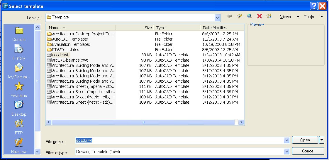
To use a template file to begin a new drawing, select "File" from
the pull-down menu, then "New." The "Select template" dialogue
box will open up as shown in the following illustration:
Templates
have the filename extension of *.dwt. Select your template file from the list
and pick "Open." To continue drawing, save it to any name and folder
you want using the "Save" command. The Template file you started with
will now be automatically saved as a DWG file.
MAKING A NEW TEMPLATE FILE:
The easiest way to make your standard settings permanent for later reuse is
to create your own Template File. Begin a new drawing, set the drawing variables
as you want them to be set, and then save the drawing as a "Template"
file for reuse to begin with on future drawings. This new file will have no
"entities" in it (lines, arcs, or circles), but it will include the
following variables:
Your list of LAYERS, with
associated linetypes, colors, and lineweights
Your preferred text styles
Your preferred dimension styles
Your preferred variable settings
Your layout settings
Viewport(s)
Name of each viewport
Scale of each viewport
Locked or unlocked status of each viewport
Plotting parameters of each viewport, such as what printer to plot to, paper
size, plot scale, drawing orientation, and plot style table (pen assignments)
Title sheet information, such as a title block
To make a new Template file in AutoCAD, follow the steps in the order as listed below:
Change the variable Startup to 1 (turn on): type startup<RET>1<RET>
Type new<RET>
Use the "Start from Scratch" method of setting up a new drawing
Select Imperial units
Using the blank drawing that automatically comes up (called "Drawing1.dwg), save it to your folder by clicking on the "Save" icon on the Toolbar (the one that looks like a floppy disk). Save it to your folder with your initials like this: [your initials]-A This will save it to H:\[your folder] as [your initials]-A.DWG. For instance in my case, I would save it to the Template folder on my H: drive as "FEH-A.DWG." The reason for the -A after your initials is to remind you that this is a template to be used for A-sized drawings (8 1/2" x 11")
Set "architectural" units type, which is feet, inches and fractions of an inch: Type UNITS<RET> Select the "Architectural" radio button.
Note that this unit type is known in the industry as "Imperial" units. This type of measurement system is used only in the United States, Liberia and Myanmar (Burma). All other countries in the world use the "System International" (or "SI") for drawing units. This is based on the metric system where all dimensions are measured in millimeters. The United States is slowly "inching" toward using the "Systeme Internationale" (SI system) measurement, but because our industrial base is so entrenched in the Imperial system, it will take many years to accomplish. The U.S. Government has mandated that all drawings made for federal construction projects use both the Imperial and the SI system beginning in 1993. AutoCAD is flexible in that one may begin using Imperial units of measurement, and switch to metric units later by selecting "Decimal" units under the "Units Control" dialogue box and scaling the drawing up by a scale factor of 25.4 (since there are 25.4 millimeters in a inch).
Select Precision at 1/32" and Click OK
Create layers to use in
future drawings. Either select the icon for the Layer Properties Manager on
the toolbar. Make all layers in the following layer list:
Assign colors to each layer. To do this, in the layer dialogue box, click on one layer at a time to select that layer for assigning a color to. This will highlight that individual layer name. Then select the empty square box to the right of the highlighted layer which is located under the heading "C..." at the top of the list of layers. The heading "C" stands for Color. Note that the full word "Color" will appear at the top if you slide the line to the right of the letter "C..." towards the right. You can slide the other headings over also, showing the full headings for each column. Another dialogue box will now appear which will show swatches of the standard nine colors across the top of the screen and a 255 color array on the screen. Select a color by either typing in the color number and then picking "OK" or by clicking on one of the color swatches. After you have assigned a color to the layer, pick the "OK" button and you will be returned to the Layer and Linetype Properties dialogue box with the square to the right of the selected layer now being colored with the assigned color. Repeat this process until all colors have been assigned to all layers. If the same color is to be assigned to more than one layer, you can select more than one layer for highlighting by holding the <Ctrl> key on the keyboard down and picking more layer names. If you made a mistake and included a layer you do not want to assign the color to, simply hold the <Ctrl> key down and pick it again, the highlighting will go away, and it will be "unselected." When you have picked all layer names to which the same color should be assigned, pick one of the square boxes to the right of one of the highlighted layer names to bring up the "Select Color" dialogue box. Note that the color WHITE should not be used for any layers you create. It should be reserved for the "0" layer only, which is to be used in creating blocks. The "0" layer has the peculiar characteristic that when it is assigned to a block will change its colors in accordance with the color of the layer on which that block is inserted. It is therefore called the "Chameleon" layer, because it acts like the chameleon lizard which changes its color depending on the color of the object it is lying on.
Assign linetypes to layers:
Most layers will have the "Continuous" linetype (i.e. a solid, non-dashed
line) assigned to them. However, you may note in the chart of standard layers
that there are several layers which will need to have special linetypes assigned
to them. To change the linetype assigned to a layer, click on the layer name
to highlight it. Then click on the word "Continuous" at the right
end of that line. This will bring up a list of linetypes. If the name of the
linetype you want to assign to the layer does not appear on the list, click
on the "Show Linetyles in File" button and select it from the list.
Note that the new name of the linetype will now be shown in the list at the
right end of the layer name.
Assign lineweights to each layer. By convention this is done with millimeter
line widths.
Assign plot styles to each layer - this should be "Style 1."
Set the current layer: Highlight the layer on the list you want to make current and right click - pick "Make Current." You should make A-Wall layer current for the template, because that is the layer you would want to use first.
Set the following AutoCAD variables to their correct values:
Type MIRRTEXT <RET> 0 <RET>. This will make text "right reading" even if it is mirrored using the "mirror" command.
Type FILLETRAD <RET> 0 <RET> This will make fillet radius zero to start with. (If you change this during the course of making the drawing, be sure to change it back to zero, otherwise you may try to cleanup line intersections using the fillet command and find that the cleaned up intersections will have a radius.)
Type VIEWRES <RET> <RET> 20000 <RET> This will make circles and arcs appear smooth. (The default value is 200 which makes circles look like octagons on the screen)
Type UCSICON<RET>ON<RET> This will turn the UCS icon on (make it visible).
Type UCSICON <RET> OR <RET> This will place the "User Coordinate System" (UCS) icon at the drawing or UCS "origin" point (0,0,0).
Type UCSICON <RET>P<RET> then select the radio button next to the 2D UCS Icon Style in the dialogue box that will appear. This is a much more informational icon style.
Type REGENAUTO<RET>ON<RET> This will eliminate that annoying AutoCAD Alert box asking, "About to regen -- proceed" whenever you zoom to extents or into a small area.
Type VISRETAIN<RET>1<RET> This will permit you to keep the layer visibility in the xref the way you have it set in the xref, rather than the host drawing.
Type DIMASSOC<RET>2<RET> This will permit associative dimensioning in paper space which will attach dimensions to their model space entities.
Type UCSFOLLOW<RET>
0<RET> This will prevent AutoCAD from automatically switching to the current
plan view when you create a new User Coordinate System switch to one that is
already made.
Set OSNAP functions. Right-click on the word OSNAP at the bottom of the drawing.
Select the menu item "Settings." This will bring up the "Drafting
Settings" dialogue box. Under the "Object Snap" tab, turn the
following Object Snap Modes On (and turn off the others): Endpoint, Midpoint,
Center, Node, Quadrant, Intersection, Perpendicular, and Nearest.
Staying in the same dialogue box, select the Polar Tracking tab. Change the Increment Angle to 45 degrees. Check the box "Additional angles" and set them to 45.00, 135.00, 225.00, and 315.00. Under the section "Polar Angle measurement" select the radio button "Absolute." Click OK.
At the bottom of the drawing, turn on "GRID," "POLAR" "OSNAP." Turn off "SNAP," "OTRACK," "DYN" and "LWT."
Set Text styles
Pick "Format" from the pull-down menu.
Pick "Text Style..." (This brings up the "Text Style" dialogue
box).
Select the Standard Style from the "Style Name" list
Select the romans.shx font from the "Font Name:" drop down list. To
get to the r's in the list quickly, move the cursor to the list and type r.
Click on the "New"
button.
In the "New Text Style" dialogue box that appears, type in the word
DIMENSIONS after "Style Name." Click OK.
Select the romans.shx font from the "Font Name:" drop down list.
Double click on the number in the box after the words "Width Factor:"
and type in the number .75.
Click on the "Apply" button
Click on the "New"
button again.
In the "New Text Style" dialogue box that appears, type in the word
NOTES after "Style Name." Click OK.
Select the romans.shx font from the "Font Name:" drop down list.
Double click on the number in the box after the words "Width Factor:"
and type in the number 1.
Click on the "Apply" button
Click on the "Close" button (the NOTES text style will be the so-called
"current" text style)
If you wish to go back and make another text style current, simply pick "Format" from the pull-down menu, then pick "Text Style..." and then select the style you what to make current from the drop-down box under the words "Style Name" and then click on the "Close" button.
Set dimensioning styles:
Set up the first dimension
style
Pick "Format" from the pull-down menu
Pick "Dimension Style..." (this brings up the dimension dialogue box).
Click on the word "STANDARD" in the "Name:" box.
Click on the "New" button.
On the "New Style Name" line, type in a name for the dimension "style"
you want to create. Let's assume that you are drawing a plan or elevation to
be plotted at 1/4" = 1'-0" scale and you need a dimension style which
will have all of the parameters set so that it will look correct at that plot
scale. Therefore, just to be descriptive, name this style "48." (48
is the plot scale factor for 1/4" = 1'-0" scale drawings)
Pick the "Continue" button.
Click on the "Lines and Arrows" tab.
In the "Arrowheads" portion of this dialogue box, make the following
changes:
Change 1st and 2nd arrowheads to "Architectural tick"
Change leader arrowhead to "Right angle"
Change arrow size to 3/32
In the "Dimension Line" portion of this dialogue box in the upper
left hand corner, make the following changes:
Change "Color" to "Bylayer"
Change "Lineweight" to "Bylayer"
Set "Extend beyond ticks" to 3/32
Change Baseline Spacing" to 0
In the "Extension Lines" portion of this dialogue box, make the following
changes:
Change "Color" to "Bylayer"
Change "Lineweight" to "Bylayer"
Change "Extend beyond dim lines" to 3/32
Change "Offset from Origin" to 1/32
In the "Center Marks for Circles" portion of this dialogue box, make
the following changes:
Make sure that the "Type" is set to "Mark"
Set "Size" to 3/32
Click on the "Text" tab
In the "Text Appearance" portion of this dialogue box, make the following
changes:
Set "Text Style" to "DIMENSIONS" (this assumes that you
have already created a text style by this name)
Change "Text Color" to "Bylayer"
Change "Text Height" to 3/32
In the "Text Placement" portion of this dialogue box, make the following
changes:
Set "Vertical" to "Above"
Change "Offset from Dimension Line" to 1/32
In the "Text Alignment" portion of this dialogue box, pick the "Aligned
with Dimension Line" radio button
Click on the "Fit" tab
In the "Fit Options" portion of this dialogue box, select the "Always
keep text between ext lines" radio button
In the "Text Placement" portion of this dialogue box, select the "Over
the dimension line, without a leader" radio button
In the "Scale for Dimension Features" portion of this dialogue box,
make the following changes:
Make sure that the "Use overall scale of:" radio button is selected
Change the number in the box to the right of this radio button to 48
In the "Fine Tuning" portion of this dialogue box, check the box "Always
draw dim line between ext lines"
Click on the "Primary Units" tab
Under the "Linear Dimensions" portion of this dialogue box, make the
following changes:
Select "Architectural" unit format
Set "Precision" to 1/16"
Select "Diagonal" "Fraction Format"
Under the "Zero Suppression" portion of this dialogue box,
Check the "0 Feet" box
Uncheck the "0 Inches" box
Go back and click on the "Text" tab
In the "Text Appearance" portion of this dialogue box, set the "Fraction
height scale" value to 0.75
Pick OK at the bottom of this dialogue box. This will bring you back to the
"Dimension Style Manager" dialogue box.
Select the "Set Current" button.
Select the "Close" button at the bottom of the dialogue box.
Set up additional dimension styles for other viewport scales
This completes the set
up of one dimension style. It will provide a good architectural appearance of
dimensions, angles, and leader lines for drawings plotted at a plot scale of
1/4"=1'-0". You can now use this set up to create other dimension
styles for other plot scales. To do this, open the "Dimension Style Manager"
dialogue box (if it is not already open) and click on the "48" style
to highlight it, then click on the "New" button. In the "New
Style Name" box, type in a name for the new style you want to create, such
as "96". Then click the "Continue" button. Click on the
"Fit" tab and change the value of "Use overall scale of:"
to 96. This would make it correct for 1/8" = 1'-0" scale viewports.
Then click the"OK" button, then the "Close" button.
The following are names and "Use overall scale of:" values for various
viewport scales:
1/16" = 1'-0":
192
3/32" = 1'-0": 128
1/8" = 1'-0": 96
3/16" = 1'-0": 64
1/4" = 1'-0": 48
3/8" = 1'-0": 32
1/2" = 1'-0": 24
3/4" = 1'-0": 16
1" = 1'-0": 12
1 1/2" = 1'-0": 8
3" = 1'-0" 4
Half size: 2
Full size: 1
1" = 1000'-0": 12000
1" = 500'-0": 6000
1" = 200'-0": 2400
1" = 100'-0": 1200
1" = 50'-0": 600
1" = 20'-0": 240
1" = 10'-0": 120
Applying dimensions in Model Space
To begin using dimensions, turn on the "Dimension" tool bar - right-click
on any other tool bar and select the "Dimension" tool bar. This has
all the tools to create dimensions on it.
Set the current layer to "A-Anno-Dims"
Set the space to "Model" space
Select the "Format" pull down menu, then select "Dimension Style..."
Select the dimension style which is appropriate for the scale of the viewport
in which the drawing will appear, for instance in a viewport scaled for 1/4"
= 1'-0" scale, select the dimension style called "48"
From the dimension tool bar select the "Linear Dimension" icon.
Snap to one of the endpoints of the line, then the other end point of the same
line - alternatively, select the line itself - AutoCAD will automatically find
its endpoints
Select a point through which the dimension line will pass
Done
To continue with a string of dimensions to the next endpoint, select the "Continue
Dimension" icon
Continue picking endpoints
When done with the string, hit two <RET><RET> keys
Editing dimensions
If you want to edit text on a dimension, click on it and the "Modify Properties"
window will display its properties. Click on the plus sign to the left of the
word "Text". In the slot to the right of the "Text Override"
type in the text you want to display on the dimension. To display text with
the measured dimension, type the text and then <>. The "<>"
will display as the measured dimension. If you want to have multiple lines of
text, type \P where you want to start a new line. Note that the P must be in
upper case.
Using grips to change location
of dimension lines, dimension text,
and extension line origin points:
If you select a dimension string at the Command: prompt, five grips will be
placed on the dimension string, one at the insertion point of the text (at its
center), one at each end of the dimension line where it crosses the extension
lines, and one at the origin point of each extension line. You can make any
of these grips "hot" and drag them to another location.
To change the length of a dimension line, make one of the grips at the extension
line origin hot and move it parallel to the dimension line. The dimension text
will always be automatically updated to read whatever the new length is.
To change the location of a dimension line itself, make one of the grips hot
on the dimension line and drag it to a new location.
To change the location of the dimension text (this is a common requirement),
make the grip on the dimension text hot and drag it to a new location. Note
that if you drag it to a location which is near to or on the dimension line
itself, a break will automatically be placed in the dimension line to allow
for the text to be able to be read without interference from the dimension line
crossing through it.
Paper Space Dimensions
Dimensioning Variables
for Paper Space Dimensions
Set variable DIMASSOC = 2 (in Command" prompt area, type in ASSOC <RET>
2 <RET>)
Create a new dimension style and name it "psdim"
Select the "Format" pull-down menu
Select "Dimension Style..."
Click on one of the model space dimension styles already created - this will
set all of the other variables correctly
Click on the "New…" button
Type in the name of the Style in the "Create New Dimension Style"
dialogue box: PSDIM
Click the "Continue" button
Select the "Fit" tab
In the box called "Scale for Dimension Features" select the radio
button called "Scale dimensions to layout (paperspace)"
Select "OK" button
Select "Set Current" button
Select "Close" button
Change to paperspace - to do this, select one of the tabs at the bottom of the
drawing image area, other than the Model" tab
Make sure that the viewport is set to the correct scale on the "Properties"
Palette.
Lock the viewport display on the "Properties" Palette.
Dimension the objects in paperspace - be sure to osnap to end points or midpoints
of object being dimensioned. Do not osnap to end points of another dimension
line. Note: you cannot dimension endpoints of AEC walls in paper space - You
can only dimension lines, polylines, blocks, arcs and circles in paper space!
Now experiment by double clicking inside the viewport to get you into the model
space displayed by that viewport. Click on a line and move its endpoint grip.
Go back to paperspace (by clicking the "Paper" button at the bottom
of the screen). Switch to paperspace and see that it changed the dimension.
CREATE A LAYOUT
Each Layout that you create will be carry with it the following elements:
A unique name of each Layout as displayed on a Tab at the bottom of the drawing
One or more Viewports including a scale for each viewport, locked or unlocked status for each viewport, and plotting parameters for each viewport, such as what printer to plot to, paper size, plot scale, drawing orientation, and plot style table (pen assignments)
Drawing entities you want to have visible and printable in the Layout, such as drawing title information and a border
Click on the "Layout1"
tab at the bottom of the drawing. This will bring you into "Paper Space"
and allow you to set up viewports and draw a border.
By default you always are drawing in so-called "Model Space," which
is where you should be to draw the 3-dimensional "model" of the building.
However, the border of the sheet should be drawn in so-called "Paper Space."
"Paper Space" is a special 2D drawing mode in which you can group
various "views" of your 3D "model" of the building for plotting
purposes. These views are typically plan, elevation, section, and perspective
and are created in "viewports" drawn in the Paper Space Layout. Since
the model of the building is the only drawing, when the model is changed, the
plans, elevations, and sections are automatically changed in their viewports.
The great advantage of working this way is that you can visualize the building
or space as it will actually exist in three dimensions. This tool will virtually
eliminate the old difficulty of "turning the corner" in visualizing
the building design.
Delete the viewport entity that AutoCAD creates by default - you may have to
zoom to extents to see it
Set the current layer to A-ANNO-VPRT
Create a new paper space viewport. Type MV (alias for the command MVIEW which means "Make Viewport"). Type 0,0<RET>10,8<RET> This will establish a viewport size as well as a maximum size which can be plotted on letter sized paper with the HP 5si LaserJet printer located in rooms AT150C and AT135. The viewport size can readily be changed later by clicking on the viewport and moving the grips.
Right-click on the viewport and select the "Properties" command. This will bring up the Properties Palette, if it is not already turned on. Click on the drop down list in the "Standard Scale" item in the properties list (under the "Misc" heading towards the bottom of the list). Select 1/4" = 1'-0". This will make the viewport scaled to 1/4" = 1'-0" scale when it is plotted.
Place the drawing title in the border. Toggle the <Caps Lock> key on before you type the title, so that it appears in all UPPER CASE LETTERS. It is OK to use both upper and lower case letters, but the most typical method of putting text in an architectural drawing is to use all caps (i.e., "upper case"). Type Dtext <RET>. Then type J<RET> C<RET>. Place the cursor on the bottom edge of the viewport until an equilateral triangular symbol appears - that is how you know that you are going to OSNAP to the "midpoint" of this line. "Pick" it with the left button of the mouse. Type 1/4<RET><RET>. Now type your name, the date in this format: "17 OCT 2006," the school name, the course number, the instructor's name, and the exercise number on one line to create an identification title for the drawing. After typing in this line, type <RET><RET> to finish the text command. Note that there should be two or three spaces between each main part of the title.
Now move the title up above the bottom line of the border: Type M<RET> L<RET><RET> 0,.5 (note that this is "0.5" or 1/4] <RET><RET> Note that "M" is the easily typed "alias" for the command "Move," and "L" is the abbreviation for "Last" which means the "last" entity created, or the line of text.)
Right-click on the Layout1 tab at the bottom of the drawing. Select "Page Setup..." from the menu that will appear. This will bring up the "Page Setup" dialogue box. Select the "Plot Device" tab first. After the word Name: there is a drop-down list. Pick the HP5Si plotter from the list.
Select from the "Plot style table (pen assignments)" drop down list the plot style "monochrome.ctb."
Click on the "Layout Settings" tab.
Select "letter" paper size and "landscape" drawing orientation. Under "Plot Area" select "Extents." Under "Plot Scale" select 1:1.
Right-click on the Layout1 tab at the bottom of the drawing again. Select "Rename" from the menu. Type "A" in the Rename Layout dialogue box and pick OK. This layout will be called "A" because it will remind you that it is setup for A-sized drawings.
Return to "Model Space: Click on the Model tab at the bottom of the drawing. Note that the word PAPER now reads MODEL at the bottom of the drawing.
Set the current layer to A-WALL.
Change Startup to start with a template file: Type startup <RET> 0 <RET>
Save the file you have just created as a "Template" file, which can be used as a start for your other drawings. To do this, pick "File" from the pull-down menu, then "Save As". When the "Save Drawing As" dialogue box appears on the screen , click on the drop-down box labeled "Files of Type." Pick the "AutoCAD Drawing Template (*.dwt)" choice. You will need to change the folder to which it will be saved to the M:\_Architecture\[your name] folder by clicking in the "Save in" drop down box at the top, then pick the "Save" button. Next, a "Template Description" dialogue box will pop up. In this box, you can type in a description for your Template file for future reference. You could put in the fact that it is to be used for A-sized drawings, the date it was created, and the course it was made for, as an example. Then click on the "OK" button.
Copy the template file to your flash drive for safe keeping.
This Template file may be edited at any time to add other items or change variables which you want to use in your future drawings. To open the template file for editing, in AutoCAD, either type new<RET> or select the icon in the tool bar that looks like a blank sheet of paper (the QNew command). A list of template files which are stored in the default Template File folder location will appear, but your template file will not be on that list. Pull-down the down arrow to the right of the "Look in:" box and navigate to your folder on the M: Drive. Select your template file to open it. Make the changes you want and then re-save-as a Template file. To do this, pick "File" from the pull-down menu, then "Save As". When the "Save Drawing As" dialogue box appears on the screen, click on the drop-down box labeled "Files of Type." Pick the "AutoCAD Drawing Template (*.dwt)" choice. Change the folder to which it will be saved to the M:\_Architecture\[your name] folder by clicking in the "Save in" drop down box at the top, then pick the "Save" button.
You can make several template
files. The one you just created will be used to plot A-sized drawings at 8 1/2"
x 11" size on a laser-jet printer. You could do another similar template
(using this one as a starting point) for larger plot formats, such as 18"
x 24" (C-sized drawings) and 24" x 36" (D-sized drawings).
PROFILES
A "profile" is a personalized file with a filename extension of *.arg that contains information about how you want the screen to look and information on where AutoCAD will search for files while you are working in AutoCAD. The Profile file can be saved and then loaded in the future when you begin a new AutoCAD session. This will automatically restore your personal settings. Profiles also include links to the CUI file you want to use.
How to create a Profile:
1. Right-click in Command: Line & select "Options..." from right-click menu
2. Click on the "Files" Tab
Click on the + sign to
the left of "Support File Search Path" on the list. This will open
the list of folders which are on the path of searching for files that will be
inserted or externally referenced into the drawing. You can add your folder
- select the "Browse" button and find your folder on drive H:\.
The "Move Up" button will allow you to reposition the folders to make
the ones at the top of the list be searched first - therefore if you have the
same file name in two folders, the one in the folder at the top of the list
will be found first.
Click on the + sign to the left of the "Template Settings" on the list. Then click on the + sign to the left of the "Drawing Template File Location." Click the Browse button and find the folder where your template file is located.
Click on the + sign to
the left of the "Automatic Save File Location." Click on the "Browse"
button and browse for the folder where you want to save your temporary save
files. An automatic save will have the filename extension of ___.sv$ which is
created automatically by AutoCAD and by default is saved to the folder C:\Documents
and Settings\AT150\Local Settings\Temp\. These files are automatically deleted
after you turn the computer off and on again, so it would be better to save
them to your folder on the network drive (drive H:). Then you can keep them
and always go back to them later.
3. Click on the "Display" tab.
Click on the "Colors..." button. Select "Layout Tabs Background (paper). Pick Black for the color. Click Apply and Close button.
Under the section labeled "Layout Elements" uncheck "Display printable area " and "Display paper background"
Slide "Crosshair size"
bar to 100%
Note that most of the choices on the right side of this tab "Display resolution"
and "Display performance" have an blue AutoCAD icon to the left side
of the choices. This means that you can change these variables for this session,
but the permanent values are contained within the drawing you are working with.
Therefore, you should make these changes in your Template file, not in the profile.
4. Click on the "Open and Save" tab.
Under the section labeled "File safety precautions" change the Automatic Save to 10 minutes between saves. This will create an automatic save with the filename extension of ___.sv$ which is created automatically by AutoCAD at 10 minute intervals and saved to your folder that you set in step 2 above.
Under the File Open section,
change the number of recently-used files to list to 9 and check box labeled
"Display full path in title."
5. Click on the "Plot and Publish" tab.
Under the section "Default plot settings for new drawings" select the radio button "Use last successful plot settings."
Click on "Plot Style
Table Settings..." button in lower right hand corner. Select the radio
button "Use color dependent plot styles." Select the monochrome.ctb
plot style from "Default plot style table" drop-down list. Click OK.
6. Click on the "User Preferences" tab.
Under the "Windows Standard Behavior" section, check box labeled "Shortcut menus in drawing area."
Click the button "Right-Click
Customization" and check box labeled "Turn on time-sensitive right
click:" Click "Apply and Close." Click OK.
7. Click on the "Drafting" tab.
Under the "AutoSnap Settings" section, check boxes labeled "Marker," "Magnet," and "Display Autosnap Tooltip."
Slide Autosnap marker size slightly to the right to increase its size.
Under the "Object
Snap Options" section, check box marked "Ignore hatch objects."
8. Click on the "Selection" tab.
Slide the Pickbox size
slightly to the right to increase its size.
9. Click on the "Profiles" tab.
Select the "Add to List..." button. Type in a profile name that you want to create in the "Add Profile" dialogue box. Type in a description. The name of that new profile will appear in the "Available Profiles" list.
Click on the newly added profile on the list and select the button "Set Current." This will make your new profile the current one.
Select the "Export" button. Browse for your folder on your H:\ drive and type in the name you want to give to your profile. It should be the same name you gave it when you added it to the list of available profiles (although it does not have to be). AutoCAD will automatically append the filename extension *.arg to whatever name you give it when you export it. The purpose of exporting the profile is to be able to use it at another computer and at a future drawing session.
When you want to use this profile again in the future, right-click in Command Line & select "Options..." Select the "Profiles" tab. Select the "Import" button and find your profile (the .arg file). Double-click on its name. This will insert the name of the profile in the "Import Profile" dialogue box. Select "Apply and Close" button.
The
imported profile name will now appear in the "Available Profiles"
list. Click on it and then click the "Set Current" button. Click OK.