You will notice that the drawing screen has many parts to it and can be somewhat confusing at first. There is a bar on the top of the screen which is a standard Windows feature. This identifies the fact that the program running in the "window" is AutoCAD and lists the name of the current drawing. If you have not saved the drawing yet, AutoCAD simply calls it "Drawing".
Just below the top bar is a row of words. This is the "pull-down menu" that contains almost all commands used to draw or change drawings.
Below the pull-down menu is one or more docked "toolbars," which provide a simpler and more "right-brained" method of selecting commands. One of these toolbars is the so-called "Object Properties" toolbar which will no doubt get lots of use by you. It allows you to create new "layers" (or transparent sheets) to draw on, assign a color to the lines drawn on any layer, make a layer one on which you are currently drawing, and turn on or off selected layers to control their visibility in the drawing. There is only one layer pre-defined in AutoCAD, called the "0" layer. This is the layer that is "current" when you begin a new drawing. You may create any number of additional layers as you make the drawing, thereby placing walls on one distinct layer, doors on another, text on another, etc. A description on how to create layers and draw on them is given later in this manual.
Below the docked toolbars is a large black area which is the area in which the drawing will be created. If you move the pointer (the arrow which is controlled by the mouse) into this arrow, it changes shape from and arrow to a crossed pair of lines with a small square at their intersection, called the "crosshairs," which can be moved around and used to select a point or an object on the screen.
Below the drawing area is a thin horizontal window which is called the "AutoCAD Command Line window." It shows your typed input as you are working and provides you with useful "prompts" to guide you in making choices during your input of commands. Normally the last three lines of activity is shown in this window, but the area can be expanded or contracted by placing the pointer on the top edge until a double-headed arrow appears and moving it up or down. The window can also be made to float as a separate window by dragging it from its "dock," or it can be turned off completely (this is not recommended).
At the lowest point of the AutoCAD screen is the "Status Bar." This includes several "toggles" and tells you the current state of the drawing environment. The toggles allow you to easily change the environment. From left to right these toggles are as follows:
The left-most is the coordinate dial. It indicates the location of the crosshairs in three-dimensional space. It has three states, which can be changed by double-clicking on it. The first state shows the X, Y, and Z coordinates of the crosshairs location in Cartesian coordinate system (X,Y,Z). The second state shows the location of a second point with relations to a first point in "polar" coordinate system (distance and angle). The third state is turning the coordinates read-out off so they do not update with the crosshairs movement. When the coordinate dial is off, it is also "greyed out." It does not harm anything to leave the coordinate dial turned on, and in fact it can be a help in locating where you are in space on the drawing. Notice that as you move the crosshairs around the drawing screen, the coordinate dial will change its read-out. Do not use the coordinate read-out as a means of selecting the locations of the endpoints of lines in your drawing, since they will not be as accurate as you will need. There are better ways of achieving precision when locating points. Accuracy is much more important in CADD drawing than it is in manual drafting techniques. The coordinate dial shows only approximate locations.
The next toggle button says "SNAP." When Snap is on, you can only draw lines to or from one of the pre-set grid points on your drawing. When it is turned off you can draw a line anywhere. Snap should normally be turned off in architectural drawing. You can turn Snap off or on by double-clicking on the button. When the SNAP toggle is turned off, it is "grayed out."
The next toggle button says "GRID." When Grid is on, you will be able to see a rectangular pattern of non-printing dots on the screen which will be spaced at a distance you can set. They are used only as a rough guide for drawing and have no direct interference or assistance with your drawing. You can turn Grid off or on by double-clicking on the button.
The next toggle button says "ORTHO" on it. When it is toggled on, "Orthomode" will be turned on, which will permit drawing only horizontal and vertical lines. This is very useful on many occasions, which is why there is a button for it. When the ORTHO toggle is turned off, it is "grayed out." The keyboard function key F8 will also toggle Orthomode on and off.
The next button says "OSNAP" on it. This button will toggle on or off the "object snapping" function, which will enable you to snap an endpoint of a line to another endpoint of another line, for example. You can turn Osnap off or on by double-clicking on the button. When the OSNAP toggle is turned off, it is "grayed out."
The next button says "Model" on it. When toggled on you are drawing in pure "Model Space." If you double-click the word "MODEL," the word "MODEL" changes to the word "PAPER." This means you are now drawing in "Paper Space." You will learn more about these two drawing spaces in exercise Number 1.
COMMAND INPUT
When you begin a new drawing
or begin editing an existing drawing, the bottom of the monitor screen
area normally has the word "Command:" in the lower left corner of
the screen. This is the so-called "Command Prompt." What it means is that
it is asking you for your command input. You can type in your command here,
or input it using several other methods. Three lines of your input and/or
command prompts are usually visible at the bottom of the screen. If you
want to review previous prompts or your responses to them, you can either
scroll up the command window, or "flip the screen" to a full text
window by typing the <F2> key on the keyboard (or, alternatively,
hold the <Alt> key down and click the <Tab> key once). This will
temporarily turn off the drawing (or graphics window) and
show you a screen full of text. To return to the graphics window after
looking at the text, type the <F2> key again. The illustration below
shows the AutoCAD screen at the start of a drawing.
1. Toolbars
When you begin a new drawing or begin editing an existing drawing, several so-called "Toolbars " will appear on the screen. They are rectangular boxes that contains "icons" (pictures) which represent AutoCAD commands. When you place the cursor over one of the icons, a word or words will appear at the cursor which shows in words what the command is under the cursor if you do not yet recognize the meaning of the icon itself. The toolbar can be moved around to any position on the screen by placing the cursor on the bar at the top of the toolbar, clicking the left button of the mouse and holding it down while moving the cursor to another location. The toolbar will be "picked up" by the cursor and moved to wherever the cursor takes it. The toolbar can be made to align to the sides of the drawing area or be turned off altogether. There are four states of appearance of the toolbar: floating, docked to left, right, top or bottom side of the screen, or turned off. The toolbar is the most useful way of selecting commands because it is considered to be a "heads up" approach to drawing. You do not have to look down at the keyboard or a digitizer pad to enter a command.
An example of the toolbar on the AutoCAD screen is shown below. If the icons do not look exactly like the ones on your screen, do not worry. They can easily be customized and changed to add the commands you yourself need. Everyone works slightly differently when drawing, and the toolbar is your best way of making the command input simple for your own way of working.
To change the meaning of
one of the toolbar icons, place the cursor over it and click the right
button of the mouse. You will get a long menu of possible commands. Double-click
on the one you want with the left button of the mouse.
2. Pull-Down Menu
Another possible method of
command input is the "pull-down menu" (sometimes called "pop-up menu")
at the top of the screen. A sub-menu associated with each of the words
will appear when one of the words is "picked" with the left button of the
mouse. Then any command on the "pulled-down" list of words may, in turn,
be "picked," thus invoking the desired command. The table below shows the
list of standard pull-down menus and their sub-menus.
| File | Edit | View | Insert | Format | Tools | Draw | Dimension | Modify | Help |
| New. . . | Undo | Redraw | Block ... | Layer ... | Spelling | Line | Linear | Properties ... | AutoCAD Help Topics |
| Open. . . | Redo | Regen | External Reference... | Color ... | Display Order > | Array | Aligned . | Match Properties | Quick Tour |
| Save. . . | Cut | Regen All | Raster Image ... | Linetype ... | Inquiry > | Construction Line | Ordinate | Object > | What=s New |
| Save As. . . | Copy | Zoom > | 3D Studio | Text Style ... | Load Application ... | Multi Line | Radius | Erase | Learning Assistance |
| Export... | Copy Link | Pan > | ACIS Solid | Dimension Style ... | Run Script ... | Polyline | Diameter | Copy | Connect to Internet |
| Printer Setup. . . | Paste | Aerial View | Drawing Exchange Binary ... | Point Style ... | Display Image > | 3D Polyline | Angular | Mirror | About AutoCAD |
| Print Preview | Paste Special... | Model Space (Tiled) | Windows Metafile ... | Multiline Style ... | External Database > | Polygon | Baseline . | Offset | |
| Print... | Clear | Model Space (Floating) | Encapsulated Postscript | Units ... | Object Snap Settings ... | Rectangle | Continue | Array | |
| Drawing Utilities | Paper Space | OLE Object | Thickness | Drawing Aids ... | Arc > | Leader | Move | ||
| Send... | Tiled Viewports > | Drawing Limits | UCS > | Circle > | Tolerance ... | Rotate | |||
| <here will be a list of the last 4 drawings you have opened> | Floating Viewports > | Rename ... | Grips ... | Donut | Center Mark | Scale | |||
| Exit | Named Views | Hatch. . . | Selection ... | Spline | Oblique | Stretch | |||
| 3D Viewpoint > | Text > | Object Group ... | Ellipse > | Align Text > | Lengthen | ||||
| 3D Dynamic View | Dimensions > | Tablet | Block > | Style | Trim | ||||
| Hide | Customize Menus ... | Point > | Override | Extend | |||||
| Shade > | Preferences ... | Hatch ... | Update | Break | |||||
| Render > | Boundary ... | Chamfer | |||||||
| Display | Region | Fillet | |||||||
| Toolbars | Text > | 3D Operation | |||||||
| Surfaces > | Boolean | ||||||||
| Solids > | Explode |
Note: The ">" means that when the command is selected, a "cascading" sub-menu will appear from which you will need to make a selection before any action is initiated. The ". . ." means that when the command is selected, a dialogue box will appear to prompt you to make a further selection of commands.
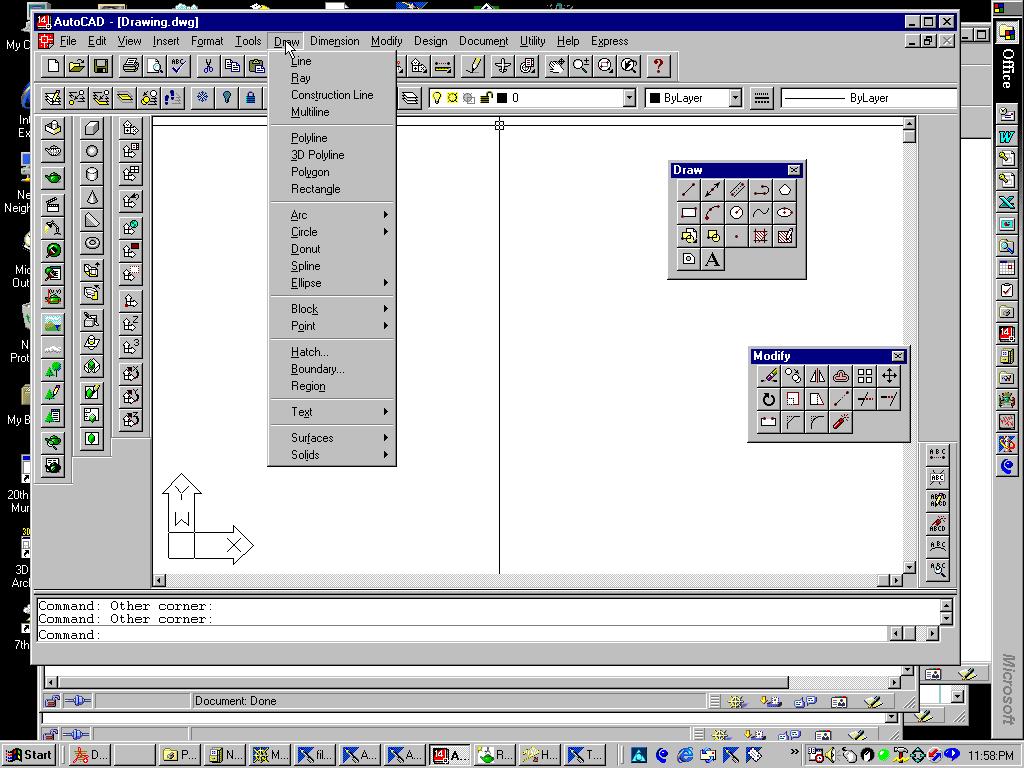
The following illustration
shows one possible arrangement of the AutoCAD desktop with all three types
of menus illustrated: The Pull-down menu with words at the
top of the drawing area,
Docked Toolbars with icons on them
at the top, left sides, and floating Toolbars on the
right side of the screen.
3. Keyboard input of commands
AutoCAD commands may also be typed in from the keyboard (they are short) followed by a <RET>. There are many AutoCAD commands, but you will likely use only a few at the beginning stages of your learning the program. Do not let the seemingly great number of commands overwhelm you. It is not necessary to know them all to draw lines, arcs, and circles, which make up architectural drawings.
There are also one or two letter shorthand "aliases" of several of the most frequently used commands that can be typed in at the keyboard to invoke the commands. You can create your own aliases by editing the file ACAD.PGP. The standard aliases (out of the box) are as follows:
A Arc
C Circle
CP Copy
M Move
MI Mirror
-LA Layer
R Redraw
PL Pline