AutoCAD EXERCISE
DIMENSIONS
DRAWING A DOOR
HATCH (poché)
This is an exercise in using the
semi-automatic dimensioning process in AutoCAD. It will require starting a new
AutoCAD drawing file using a template drawing as a base drawing, drawing a plan
of a simple room and "hatching" the walls, drawing lines and circles, working
with layers and text, and using the dimensioning commands. The end result will
be a drawing which will be printer plotted on the HP Laser Jet printer.
- Open a new drawing using the
Triton A template.
- Immediately save it to your folder
on the M: drive with name of "today's date <your initials> 3."
Like this 2006 02 18 FEH 3.DWG
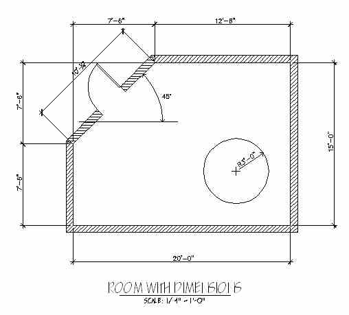
- Draw a room with internal dimensions
of 20 feet wide in the east-west direction and 15 feet deep in the north-south
direction with one corner diagonally cut off, and with a wall thickness of
8". You will be dimensioning the interior of the space.
- Draw a single left-hand reverse
bevel 3'-0" wide door 1 3/4" thick at the center of the diagonal wall
on the "A-DOOR" layer.
- Draw a circular table in the
room on the "A-FURN" layer with a radius of 3'-0".
- Make A-WALL-PATT layer current.
Draw lines from the corners of the diagonal walls, as shown on the example
attached, to separate the diagonal sections from the orthogonal sections of
the walls during the hatching. Type Bhatch <RET> or select the hatching
icon from the Toolbar (it is the icon that looks like a trapezoid with a diagonal
hatch pattern in it). Click on the "Type" pull-down box and select "User Defined".
Change the angle to 45.00. Change "Scale to 3. Select the
"Add:Pick Points " button. At the "Pick internal point" prompt,
pick a point inside the lines defining the orthogonal walls. AutoCAD will
examine the enclosed area and if it finds that there are not openings within
that area, AutoCAD will automatically place a temporary polyline inside the
boundaries enclosed within the wall thickness. When you see the dashed line
and agree with AutoCAD that this is the boundary within which you want the
hatch pattern to appear, hit a <RET>. Then click on the "Preview "
button. When you are done being amazed at AutoCAD's functionality, hit another
<RET>. Hit another <RET> to bring the "Bhatch" command immediately back
so that you can now hatch the diagonal portions of the walls. To hatch the
diagonal wall area, do the same thing as outlined above, but re-set the user-defined
hatch pattern angle to 0 degrees (that is "zero" degrees), and when
prompted for "Select internal point" pick inside the walls on both
sides of the door. Then <RET>. Then "Preview
". Then <RET>.
- Set the current layer to the
"A-ANNO-DIM" layer. This is the layer on which dimensions should be drawn.
- Fully dimension the interior
dimensions of the room, using the semi-automatic dimensioning feature of AutoCAD.
To dimension the horizontal lines select from the Pull-down menu "Dimension"
then "Linear" then OSNAP to the left-most point you want to dimension
from (the "First extension line origin"), and then OSNAP to the right
most point you want to dimension to (the "Second extension line origin").
Then pick a point through which you want the dimension line to pass. The vertical
dimensions work the same: use the "Dimension" then "Linear"
sequence from the Pull-down menu. The dimension of the diagonal wall also
works the same, but use the "Dimension" then "Aligned" sequence
from the Pull-down menu, and OSNAP to the endpoints of the diagonal line.
- To do two dimensions continued
in a string, first draw the first dimension the usual way, then select "Dimension"
then "Continue" from the Pull-down menu. Pick the next origin point
to dimension to. AutoCAD will assume that the First extension line origin
for that continued dimension is the second extension line origin from the
previous dimension.
- Note that all dimensions are
associated with their objects that are dimensioned. When those objects change
length by stretching or scaling, the dimensions will be recalculated automatically
and the dimension numbers will be redrawn. Note that you should always dimension
in Model Space, since you are making the dimensions "associate" to a full
sized object.
- Dimension the angle of the
wall. Draw a horizontal base line from which the 45 degree angle can be
measured. To dimension the angle select from the Pull-down menu "Dimension"
then "Angular" then pick the line you just drew, and then pick the
diagonal wall. Select a point through which the dimension arc will pass.
- Dimension the radius of the
table. If ORTHO is turned on, be sure it is off before you do this step.
To dimension the radius, select from the Pull-down menu "Dimension"
then "Radius." Pick the circular table of which you want to dimension
the radius The circle should be picked at the upper-right side of the circle
to get the radial dimension to be drawn as shown on the attached drawing.
Now apply a "center mark" (a pair of short crossed lines) to the circle also
to make the dimensioning complete. To do this, select from the Pull-down menu
"Dimension" then "Center Mark," then pick the circle anywhere
on its locus.
- Thaw all layers. To do this
quickly, type -LA <RET> T <RET> * <RET> <RET>.
Then type REGEN <RET>.
- Enter Paper Space - select the
Layout tab.
- In Paper Space, using DTEXT:
command with 1/4" high lettering, make the title "DIMENSIONS" below the
plan of the room
- Put a main sheet title at the
bottom of the drawing containing your name, the course number, the date, and
the instructor's name.
- Switch to floating model space.
Zoom to extents and then zoom 1/48xp.
- Switch back to paper space.
- Save the drawing: Click
on the "Save" icon on the Toolbar (the one that looks like a floppy
disk). Since you originally gave this drawing a name when you first created
it, it will be automatically saved to that same name when you pick the "Save"
button without any further input from you. (AutoCAD calls this process
a "Quick Save.").
- Plot the drawing using
the HP 5si printer. Plot the drawing in Paper Space at a scale of 1=1. Select
the "Plot" icon from the Toolbar. Set plotter parameters.
- When plotting is finished, if
you are satisfied that everything is OK, close (exit) AutoCAD, by clicking
on the X in the upper right corner of its window. You will now be back on
the Windows desktop.
- Copy the drawing to your
own USB flash disk.
END OF EXERCISE NO. 3