AutoCAD EXERCISE
BRICK BONDS
FIRST EXERCISE IN MAKING
AutoCAD "BLOCKS"
THE RECTANGULAR ARRAY COMMAND
This is an exercise in using the ARRAY
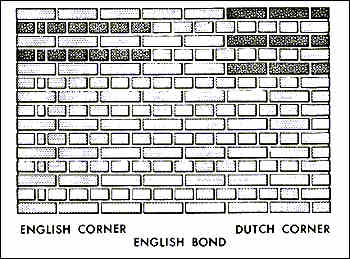
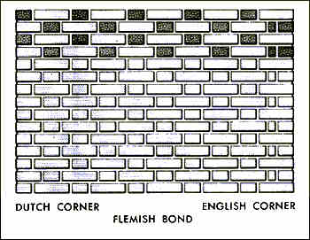
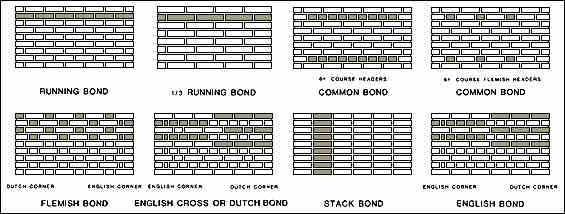
command to assist in creating a repetitive drawing of the three most-common
brick bonds, Running Bond, Flemish Bond, and English Bond. Modular brick
will be assumed in this exercise. Sizes of brick are shown on the attached
sheet. The end result will be three drawings of wall elevations showing
three different patterns of brick which will be plotted on the HP Laser
Jet printer.
- Boot the computer and start AutoCAD.Open a
New drawing using the Triton-A template.
- Immediately save it to your folder on the M:
drive with name of "today's date <your initials> 4." Like
this 2006 02 18 FEH 4.DWG
- Draw one modular brick 2 1/4" high and 7 5/8"
long. Make a "block" of this with its insertion point in the lower left hand
corner, and name it STRETCHER. See the text for a description regarding
how to make blocks.
- Draw one header brick, 2 1/4" high and 3 5/8"
long. Make a "block" of this with its insertion point in the lower left hand
corner, and name it HEADER.
- INSERT the STRETCHER block at any location
in the drawing. Use the "Array" command to array it horizontally, 1 row and
10 columns, with space between columns 8". To do this, select from the Pull-down
menu "Construct" then "Array" then "Rectangular." Select the object to array
(pick the header block), then hit a <RET> to confirm that that is the only
object you want to array. Hit a <RET> to accept the default of <1> for
the number of rows, and then type 10 <RET> in response to the prompt
for the "Number of columns (|||) <1>". In response to the prompt
for the "Distance between columns (|||):" type 8 <RET>.
- Insert the HEADER block OSNAPped to
the lower right hand corner of the right-most stretcher.
- Move the Header you just inserted over 3/8"
to account for the for the mortar joint width, as follows: Type M <RET>
L <RET> then type 3/8,0 <RET><RET>. Note this is using
the so-called "displacement" method of moving an object without using
a base point.
- Copy that entire row of bricks up one course
as follows: Type CP<RET> (or pick the "Copy" icon from the Toolbar),
then put a window around the entire row of bricks, then <RET> to confirm
your object selection set, then type: 4,2.67<RET><RET>. This
is using the "displacement" method of copying, and will copy the row of bricks
over 4" to the right in the positive X direction and 2.67" up in the positive
Y direction. Why 2.67"? That is
because each row of brick in standard American masonry practice, occupies
1/3 of 8" height, and 1/3 of 8" equals 2.67".
- Move the header from the right side of the
second row to its proper place on the left side of that row.
I bet you can figure out how to do this by now!
- Array these two rows vertically as follows:
Select from the Pull-down menu "Modify," then "Array," then
put a window around both rows, then hit <RET> to confirm your object selection
set, then type R <RET> [for rectangular array], then type 8
rows and 1 column when prompted. When prompted for distance between
rows, type 5.33 <RET>.
Why 5.33? That is because there are 2
rows, each taking up 1/3 of 8". So 2/3 of 8" equals 5.33".
- Place a STRETCHER block in a vertical
position at the top left-hand corner of the wall. Array this vertical stretcher
1 row and 32 columns with a distance between of 2.625". Why
2.625 for the distance between columns?
Just because it fits. The vertical mortar joints are a little less than 3/8"
but it probably is better with a thinner joint to keep the moisture out of
the wall. You can figure it out through a series of trial and error attempts.
The mason would likely do a little division to get the approximate number
of vertical bricks to fit in the length fo the wall and start from each end
and work toward the middle to make sure each end lines up with the wall. This
arrangement of vertical stretchers in a wall is called a "soldier course."
- Draw mortar joints using the arc command
between every brick. The best method for drawing these arcs is to use the
"Start, End, Direction" arc method. Be sure and turn POLAR off for
this to allow you to set a gentle arc to represent the mortar joints. Draw
the mortar joint between the bottom and second course, then the one between
the second and third course, and then array these two joints vertically
(5 rows and 1 column). The reason why you will need to do two joints before
arraying rather than one, is that there is a slight difference between the
bricks within each pair of rows of brick due to the rounding off of the numbers
when you originally arrayed the rows.
- The mortar joints should be assigned a color
30 so that when you print, they will be lighter than the bricks themselves.
- Draw a base line under the lowest course of
brick using a polyline with a width of 1/4". The baseline should extend out
beyond the brick wall by about 2 feet on each side, and its top should be
about 3/8" below the lowest edge of the first row of brick. You can adjust
this height using the Move command and visually selecting a second point of
displacement. If the ends of the polyline are not quite adjusted horizontally
to your liking, just pick the polyline at a Command: prompt to put
Grips on the
endpoints of the polyline. Turn POLAR on and make one of the Grips hot by
picking it and pick it again and move (stretch) it horizontally to another
location.
- Zoom the drawing to a scale of at 1" = 1'-0"
by typing the following (in Model Space): Z<RET>E<RET><RET>1/12XP<RET>
- Switch to Paper Space. Place the title "RUNNING
BOND," in 1/4" high letters, above the main sheet title. Revise main sheet
title in accordance with this exercise. Place a title at the bottom
of the drawing.
- SAVE your drawing prior to plotting [always!].
- Plot this drawing using the HP Laser Jet 5si
printer. Plot the drawing in Paper Space at a scale of 1=1. Set the
plotter parameters and pen assignments. Since you are plotting in Paper Space
and you have already selected viewports in which to hide lines, there is no
need to check the box marked "Hide Lines" in the Plot Configuration dialogue
box.
- When plotting is finished, if you are satisfied
that everything is OK, close (exit) AutoCAD, by clicking on the X in the upper
right corner of its window.
- Copy your drawing to your floppy disk.
- Repeat the steps above for the other two brick
bonds. Use this drawing as a basis for the two other ones, since your blocks
are already created. The Flemish Bond drawing should be called date
Flemish.dwg , and the English bond drawing should be called date English.dwg.
You will end up with three separate drawings and sheets for this exercise.
The Flemish bond should be capped with a Rowlock course of brick, and
the English bond with a Sailor course of brick.